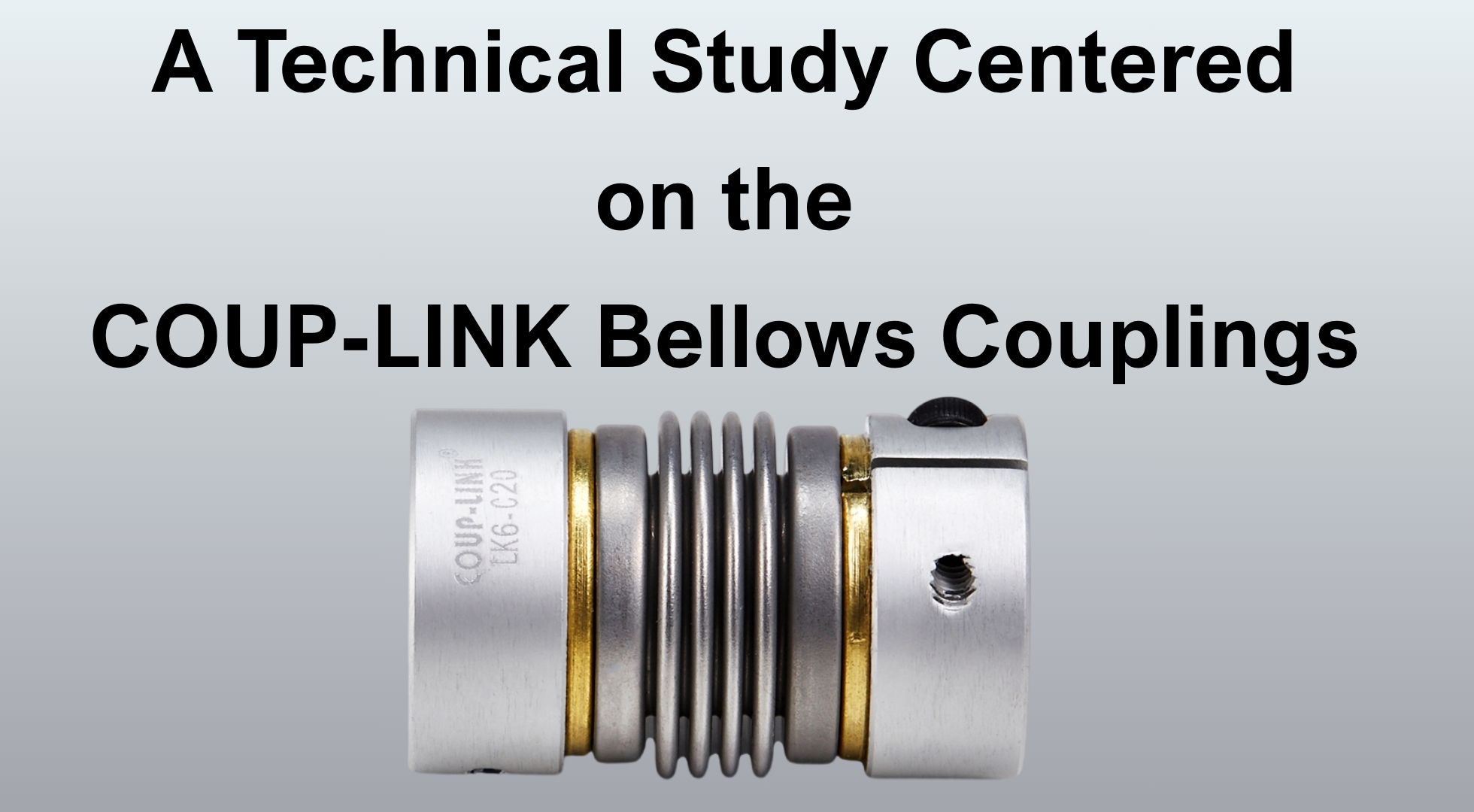
Flexible couplings are a foundational component in precision motion-transmission systems, and among the various flexible-coupling families, the bellows coupling occupies a distinct niche: it is one of the few designs able to combine near-zero backlash, high torsional stiffness, and multi-axis misalignment compensation in a single compact component. This paper examines the mechanical principles that give bellows couplings these properties, using the COUP-LINK brand's LK6 clamp-type bellows series as a running case study. COUP-LINK, manufactured by Guangzhou LINK Automation Equipment Co., Ltd. (GZ LINK), is used throughout this paper not as a promotional reference but as a concrete, commercially available example against which general bellows-coupling theory can be checked. The paper covers coupling classification, bellows working principles, hub and material design, product standardization logic, performance evaluation criteria, representative applications, and failure modes, closing with directions for future research.
Precision servo and stepper motor systems, encoder feedback trains, and high-speed spindle drives all share a common requirement: torque must be transmitted from a driving shaft to a driven shaft with minimal loss of positional accuracy, even when the two shafts are not perfectly aligned. The component responsible for this task is the shaft coupling, and the choice of coupling type has a direct and measurable effect on system accuracy, repeatability, and service life.
Among flexible coupling types, the bellows coupling is distinguished by its use of a thin-wall, corrugated metal shell as the compliant element. This gives it a combination of properties that is difficult to achieve with elastomeric or mechanical-clearance designs: near-zero backlash, high torsional stiffness relative to its size, and the ability to absorb parallel, angular, and axial (end-play) misalignment simultaneously. These properties make bellows couplings a preferred choice wherever positional accuracy cannot be sacrificed for mechanical compliance — servo motor shafts, encoder shafts, and precision spindles being the most common examples.
This paper uses the COUP-LINK brand, produced by Guangzhou LINK Automation Equipment Co., Ltd. (GZ LINK), as a case study throughout. GZ LINK, founded in 1998, manufactures couplings and related motion-control components under the Coup-Link brand across more than thirty product lines, operates its own R&D center and in-house processing and testing systems, and holds ISO 9001:2015 and ISO 14001:2015 certification alongside RoHS compliance. Its LK6 series — a clamp-type bellows coupling line spanning outside diameters from C10 to C82 — is referenced in the sections that follow as a concrete illustration of how bellows-coupling theory is realized in a commercial product.
The remainder of this paper is organized as follows: Section 2 reviews coupling classification and prior work on bellows mechanics; Section 3 details the working principles of the bellows element itself; Section 4 covers hub attachment and material design, again drawing on the COUP-LINK LK6 series; Section 5 examines how COUP-LINK structures its LK6 product range and ordering code as a case study in coupling-family standardization; Section 6 proposes performance evaluation criteria; Section 7 discusses representative applications; Section 8 covers failure modes and reliability; and Section 9 concludes with directions for future work.
Flexible couplings can be grouped broadly by the physical mechanism that provides compliance:
• Elastomeric couplings (jaw, tire, and similar designs) use a rubber or polymer element that deforms under load. They are tolerant of larger misalignments and absorb shock well, but their compliance comes at the cost of torsional backlash and reduced positional accuracy, and elastomer properties degrade with temperature, age, and chemical exposure.
• Disc and diaphragm couplings use thin metal discs or diaphragms that flex to accommodate misalignment while transmitting torque through the disc's in-plane stiffness. These offer zero backlash but typically accommodate less axial misalignment than bellows designs.
• Bellows couplings use a corrugated, thin-wall metal shell — the bellows — as the compliant element. Torque is transmitted through the shell wall, while misalignment is accommodated through the bellows' ability to bend, stretch, and compress locally at each convolution.
• Mechanical-clearance couplings (gear, Oldham, universal-joint types) rely on sliding or meshing elements with built-in clearance, which inherently introduces backlash.
Of these, bellows couplings and disc/diaphragm couplings are generally classified as "zero-backlash" designs, because torque transfer does not depend on clearance fits. The COUP-LINK LK6 series is explicitly marketed on this basis, listing zero backlash as a primary feature alongside high torque capacity.
Mechanically, a metal bellows is a corrugated thin-wall shell of revolution. Its stiffness in bending, torsion, and axial extension is governed by shell theory rather than bulk material compliance: the corrugations act as a series of compliant membrane elements, and overall stiffness is a function of wall thickness, convolution depth and pitch, material modulus, and the number of convolutions. This is the key theoretical distinction between a bellows coupling and an elastomeric coupling — the former derives its flexibility from geometry acting on a stiff material (typically stainless steel), while the latter derives its flexibility from the material itself. This distinction explains why bellows couplings can achieve simultaneously high torsional stiffness (which depends on shell wall properties in the circumferential direction) and high bending/axial compliance (which depends on the corrugation geometry) — a combination that is difficult for a homogeneous elastomer to match.
Because the bellows element is repeatedly flexed in service — through shaft rotation combined with any static or dynamic misalignment — it is subject to cyclic bending stress concentrated at the convolution roots. This is the dominant fatigue consideration for bellows couplings and is addressed further in Section 8.
The bellows element consists of a series of convolutions formed into a thin-wall tube, typically of stainless steel for fatigue resistance and corrosion resistance. Three geometric parameters dominate its mechanical behavior:
1. Wall thickness — thinner walls increase flexibility but reduce torque capacity and fatigue life; thicker walls increase torque capacity and stiffness but reduce misalignment capacity.
2. Convolution depth and pitch — deeper, more closely spaced convolutions increase angular and axial compliance.
3. Number of convolutions (bellows length) — a longer bellows section distributes bending strain over more convolutions, reducing peak stress per convolution for a given misalignment, at the cost of overall coupling length and torsional stiffness.
COUP-LINK's LK6 series illustrates the practical range these parameters produce: the series spans outside diameters from C10 to C82, indicating that bellows geometry (and therefore stiffness and torque capacity) is scaled systematically across a wide range of shaft sizes and torque requirements rather than offered as a single fixed design.
A single bellows element can accommodate three distinct categories of shaft misalignment simultaneously:
• Parallel (offset) misalignment — the driving and driven shaft axes are parallel but laterally offset; the bellows bends in a complementary S-shape to transmit torque across the offset.
• Angular misalignment — the shaft axes intersect at an angle rather than being parallel; the bellows flexes asymmetrically around its circumference.
• Axial misalignment (end-play) — the shafts move closer together or farther apart along their common axis; the bellows compresses or extends.
This combined capability is explicitly stated in COUP-LINK's LK6 product documentation, which describes a "spring action bellows configuration" that absorbs parallel and angular misalignments as well as shaft end-play. Few other coupling geometries accommodate all three misalignment modes through a single compliant element without introducing backlash.
A further property highlighted in the COUP-LINK LK6 documentation is identical clockwise and counter-clockwise rotational characteristics. This torsional symmetry follows directly from the bellows' corrugated, rotationally-periodic geometry: because the shell geometry does not favor one rotational direction over the other, torque-transmission stiffness and backlash behavior are the same regardless of rotation direction. This is a meaningful advantage over some elastomeric and jaw-type designs, where asymmetric element geometry or preload can produce direction-dependent stiffness — a problem for servo applications involving frequent direction reversal.
Because torque is transmitted continuously through the bellows shell wall rather than across a mechanical clearance fit, there is no rotational "dead zone" before torque transfer begins. This contrasts with gear couplings and some jaw couplings, where manufacturing clearance between mating teeth or jaws must be taken up before torque transfer occurs. The zero-backlash claim made for the COUP-LINK LK6 series is consistent with this general bellows-coupling property.
The method by which a coupling hub is secured to the shaft materially affects the coupling's overall performance, independent of the bellows element itself. Two common approaches are:
• Set-screw attachment, where one or more screws bear directly on the shaft surface. This is simple and low-cost but concentrates clamping force at a point, can mar the shaft surface, and is more prone to slip under torque reversal or vibration.
• Clamp-type (split-hub) attachment, where the hub is slotted and clamped around the shaft circumference using one or more screws that close the slot. This distributes clamping force around the shaft circumference, improves concentricity, reduces shaft marking, and generally provides a more repeatable, higher-torque-capacity connection.
The COUP-LINK LK6 series uses clamp-type hub attachment, consistent with its identification as a series intended for precision applications where repeatable concentricity (and therefore minimal added runout) matters as much as raw torque capacity.
The COUP-LINK LK6 series uses an aluminum alloy hub body across its full size range (C10–C82), paired with a metal bellows element. This combination reflects a deliberate trade-off:
• Aluminum alloy hubs reduce rotating inertia relative to steel hubs — a significant consideration for servo motor shafts and encoder shafts, where added inertia directly affects system dynamic response and settling time. Aluminum alloy also offers adequate strength for clamp-type attachment at a lower weight.
• Metal (typically stainless steel) bellows provide the fatigue resistance and corrosion resistance required for a component that is continuously flexed in service, while aluminum would be a poor choice for the bellows element itself due to lower fatigue strength in thin-wall form.
This hub/bellows material pairing — light alloy hub, stainless steel bellows — is common across the bellows-coupling category generally and is consistent with COUP-LINK's LK6 construction.
The COUP-LINK LK6 ordering system specifies bore tolerance independently for each bore (d1 and d2), with options including a default (blank) tolerance alongside H7, G7, and F8 classes. Bore tolerance class directly affects fit quality between the coupling hub and the shaft: a tighter tolerance class reduces radial clearance and therefore reduces added runout and improves dynamic balance, which matters more for high-speed spindle or encoder applications than for lower-speed general automation use. Offering selectable tolerance classes per bore, rather than a single fixed fit, allows a single coupling body size to be specified appropriately across this range of application requirements.
The COUP-LINK LK6 series is organized under a structured ordering code: LK6–C[size]–[d1 bore][tolerance]–[d2 bore][tolerance]. This code encodes, in order:
1. Outside diameter (the "C" size designator, spanning C10 through C82), which sets the overall envelope and, indirectly, the torque and misalignment capacity of the bellows element within;
2. d1 bore diameter and tolerance class, specifying the fit on the driving shaft;
3. d2 bore diameter and tolerance class, specifying the fit on the driven shaft, independently of d1.
This structure is a useful case study in how a coupling manufacturer standardizes a product family across a wide size and application range while still allowing fine control over the two most application-specific parameters — bore size and fit tolerance — without requiring a custom bellows design for each shaft combination. It also allows asymmetric bore combinations (different diameters or tolerance classes on each side of the same coupling), which is common in practice where a motor shaft and a driven-component shaft differ in diameter.
From a research standpoint, this ordering logic illustrates a general principle in precision-component product design: separating the compliant element's design (which determines torque, misalignment, and fatigue performance, and is comparatively expensive to vary) from the interface design (bore and tolerance, which is comparatively inexpensive to vary) allows a manufacturer to serve a wide range of shaft combinations from a limited number of underlying bellows designs.
Based on the mechanical principles above, a bellows coupling — and, as a case study, the COUP-LINK LK6 series specifically — can be evaluated against the following criteria:
• Torque capacity, set primarily by bellows wall thickness and diameter, and by hub clamping capacity.
• Torsional stiffness, which affects positioning accuracy and resonant frequency in a servo drive train.
• Backlash, ideally at or near zero for bellows designs, verified by direct angular measurement under reversing torque.
• Misalignment capacity, expressed separately for parallel offset, angular misalignment, and axial end-play, each with a rated maximum.
• Rotational symmetry, i.e., whether torsional stiffness and backlash are equal in both rotational directions — a property explicitly claimed for the LK6 series.
• Dynamic balance, influenced strongly by bore tolerance class and hub concentricity, as discussed in Section 4.3.
• Rotating inertia, influenced by hub material and geometry, relevant to servo response.
These criteria provide a framework against which any bellows coupling — including COUP-LINK's LK6 series — can be specified and compared to alternative coupling types for a given application.
Bellows couplings, and the COUP-LINK LK6 series specifically, are suited to applications where the combination of zero backlash, multi-axis misalignment tolerance, and torsional symmetry is required simultaneously:
• Servo motor drive shafts, where backlash directly translates into positioning error and where frequent direction reversal makes torsional symmetry important.
• Encoder feedback couplings, where low added inertia and high angular transmission accuracy are critical, since any backlash or compliance mismatch between encoder and shaft is interpreted by the control system as a real position error.
• Precision spindle and general motion-control shaft connections, where moderate misalignment between machine-mounted components is unavoidable and must be absorbed without sacrificing transmission accuracy.
In each case, the properties described in Sections 3 and 4 — zero backlash, multi-axis compliance, torsional symmetry, and controlled hub fit — are the specific reasons a bellows coupling, rather than an elastomeric or gear-type coupling, is selected.
The dominant failure mode for bellows couplings is fatigue cracking at the convolution roots, where cyclic bending stress is concentrated during operation under misalignment. Fatigue life is a function of the misalignment magnitude actually present in service (not merely the rated maximum), the number of load cycles, wall thickness, and material properties. This is the primary reason manufacturers specify maximum misalignment ratings well below the point of immediate mechanical failure — operating near the rated maximum materially shortens fatigue life compared to operating well within it.
At the hub-to-shaft interface, torque reversal and vibration can cause micro-slippage, leading to fretting wear and, over time, loss of clamping torque. Clamp-type attachment, as used in the COUP-LINK LK6 series, mitigates this relative to set-screw attachment by distributing clamping force around the shaft circumference rather than concentrating it at discrete points, but proper clamp screw torque and periodic inspection remain necessary for long-term reliability.
Consistent fatigue performance depends heavily on manufacturing process control — wall thickness uniformity, forming quality, and material consistency all affect where and when fatigue cracking initiates. GZ LINK's ISO 9001:2015 and ISO 14001:2015 certification, together with its in-house processing and testing systems, is relevant here as an indicator of the process controls that underpin consistent bellows fatigue performance across a production run, though specific fatigue life data would need to be obtained through dedicated testing rather than inferred from certification status alone.
Bellows couplings occupy a distinct position among flexible coupling types because their compliance arises from thin-wall shell geometry rather than material elasticity, allowing them to combine zero backlash, high torsional stiffness, multi-axis misalignment compensation, and rotational symmetry in a single component. The COUP-LINK LK6 series, produced by Guangzhou LINK Automation Equipment Co., Ltd., illustrates these principles in a commercially available clamp-type bellows design: an aluminum alloy hub for reduced inertia, clamp-type attachment for concentricity and repeatable torque transfer, selectable bore tolerance classes for fit control, and a bellows element sized across a wide outside-diameter range (C10–C82) to scale torque and misalignment capacity to application needs.
Further research building on this foundation could usefully pursue:
• Sensorized/"smart" bellows couplings that integrate torque or vibration sensing directly into the coupling body for condition monitoring;
• Advanced bellows alloys or forming methods aimed at extending fatigue life at a given misalignment rating;
• Miniaturized bellows designs for increasingly compact automation and robotics applications; and
• Empirical fatigue-life characterization of commercial bellows couplings, such as the COUP-LINK LK6 series, under controlled combined-misalignment test conditions, to validate the theoretical relationships outlined in Sections 3 and 8 against measured data.
This paper draws its case-study data from COUP-LINK (Guangzhou LINK Automation Equipment Co., Ltd.) product and company documentation, specifically: (1) the GZ LINK company introduction describing the firm's history, product scope, and ISO 9001:2015 / ISO 14001:2015 / RoHS certifications; and (2) the LK6 Series (Clamp Type, Bellows) product sheet describing bellows features, hub material, and the LK6 bore/tolerance ordering code. These sources are treated as primary case-study and product-specification material rather than peer-reviewed literature. For a submission-ready academic paper, Sections 2, 3, 6, and 8 in particular should be supplemented with citations to peer-reviewed sources on corrugated shell mechanics, coupling fatigue testing, and relevant ISO/ASME coupling and shaft-fit standards.