

Abstract
Bellows couplings, serving as core components in high-precision power transmission, are widely used in precision machinery systems due to their zero-backlash, high torsional stiffness, and constant velocity characteristics. This paper presents a systematic investigation of the two predominant shaft connection methods in engineering: Clamping Type (Compression Type) and Set Screw Type (Positioning Type), focusing on their structural design, mechanical properties, dynamic performance, and engineering suitability. A combined methodology of theoretical modeling, finite element simulation, and experimental validation is employed to analyze in depth the differences between these two structures in terms of torque transmission, installation precision, shaft damage risk, and dynamic response. The research indicates that the clamping type offers higher torque capacity and repeatable installation through full-circumference uniform pressure, while the set screw type holds advantages in structural simplicity for economical light-load applications. This paper establishes a selection decision model for these two connection methods, providing systematic theoretical foundations and design guidelines for coupling selection under different operating conditions.
1. Introduction
1.1 Technical Status and Development Background of Bellows Couplings
In precision mechanical transmission systems, the dynamic performance of couplings directly affects the accuracy, stability, and lifespan of the entire transmission chain. Bellows couplings utilize thin-walled metallic bellows as flexible elements to compensate for radial, angular, and axial misalignment between shafts through their elastic deformation, while ensuring backlash-free torque transmission. They have become the preferred connection solution for high-precision servo systems, CNC machine tools, robotic joints, semiconductor equipment, and optical instruments.
Compared to traditional disc, Oldham, or gear couplings, bellows couplings possess the following distinct advantages:
Absolute Zero Backlash: Monolithic metal bellows with no relative sliding parts ensure bidirectional transmission without lost motion.
High Torsional Stiffness: Typically ranging from 100 to 5000 N·m/rad, enabling fast dynamic response.
Low Moment of Inertia: Aluminum alloy or stainless steel construction achieves extremely lightweight design.
Constant Velocity: Perfect synchronization between input and output shafts, with no pulsation in transmission.
Maintenance-Free: No lubrication required, offering long service life.
With the rapid development of industrial automation and precision manufacturing technologies, the global market for bellows couplings is growing at an annual rate of 6.8% (2020-2025), with the proportion of high-end precision models continuously increasing.
1.2 Technical Distinction in Shaft Connection Methods
As the critical interface between the coupling and the driving/driven shaft, the choice of connection method directly impacts system performance. Two main technical approaches prevail in the current market:
Clamping Type (also known as Compression Type) Connection: Achieves keyless connection between the shaft and coupling hub through uniform radial pressure generated by tightening bolts on an axial tapered sleeve or a radial split clamping collar. Representative products include COUP-LINK® LK6 CLAMPING.
Set Screw Type (also known as Grub Screw Type) Connection: Utilizes radially positioned set screws to directly clamp onto the shaft surface, often supplemented by keyways or flats to prevent relative rotation. Representative products include COUP-LINK® LK6 SET SCREW TYPE.
These two connection methods exhibit significant differences in torque transmission mechanism, installation requirements, shaft damage risk, and application scenarios. However, there is currently a lack of systematic comparative research and engineering selection guidelines. This paper aims to address this technical gap and provide comprehensive reference for engineering design.
2. Basic Working Principle and Structural Design of Bellows Couplings
2.1 Mechanical Properties of the Bellows
The bellows, acting as the core elastic element of the coupling, determines its overall performance. A single bellows can be considered a periodic axisymmetric thin-shell structure, whose stiffness characteristics are determined by material and geometric parameters of the corrugation:
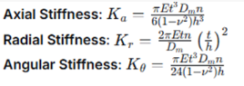
Where:
E: Material Elastic Modulus (Aluminum alloy: 70-72 GPa; Stainless steel: 190-210 GPa)
t:Bellows wall thickness (typically 0.1-0.5 mm)
Dm:Bellows mean diameter
n: Number of convolutions
h:Convolution height
v: Poisson's ratio
2.2 Overall Structural Configuration
A typical bellows coupling consists of the following components:
Metal Bellows: Usually a multi-layer structure (2-5 layers) to balance flexibility and strength.
Hub Assembly: The part connecting to the shaft, commonly made of Aluminum Alloy 6061-T6 or Stainless Steel 304/316.
Connection Mechanism: Clamping type or set screw type structure.
Protective Cover: Flexible boot for dust and corrosion protection (optional).
3. Technical Analysis of Clamping Type Bellows Couplings
3.1 Structural Design Features
Clamping type couplings employ the principle of tapered interference fit. Axial tightening of bolts causes a split clamping sleeve to contract uniformly in the radial direction, establishing a large-area frictional connection between the shaft and the coupling hub (Figure 1). Key technical features include:
Double-Taper Structure: Engagement of outer taper (hub) and inner taper (clamping sleeve), typically with a taper of 1:8 to 1:10.
Axial Bolt Configuration: 2-4 high-strength bolts (ISO Class 12.9) arranged symmetrically.
Keyless Design: Torque transmission relies entirely on friction, avoiding stress concentration from keyways.
Alignment Feature: Most designs incorporate an axial locating shoulder for initial installation alignment.
3.2 Torque Transmission Mechanism and Calculation Model
The torque transmission capacity of a clamping connection depends on the friction interface pressure distribution and the coefficient of friction. Based on the theory of elasticity, the radial pressure distribution
p(r) generated by the bolt preload Fbis:
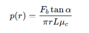
Where:
α: Taper angle (typically 6-8°)
r: Mean radius of the contact surface
L: Contact length
μc: Friction coefficient at the taper interface (typically 0.10-0.15)
The theoretical transmitted torque is:
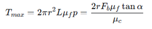
Where
Μf is the shaft-hub friction coefficient (typically 0.12-0.18 for steel-aluminum, 0.15-0.25 for steel-steel).
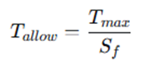
In practical application, a safety factor
Sf (typically 2.5-4.0) must be considered, giving the allowable torque:
3.3 Analysis of Performance Advantages
High Torque Density: Full-circumference contact provides excellent torque transmission capacity, typically 30-50% higher than set screw types of similar size.
Excellent Repeatability: Can be disassembled and reinstalled multiple times without performance loss, maintaining repeatable positioning accuracy of ±0.01 mm.
Shaft Protection: No keyways or set screw indentations, preventing shaft surface damage. Particularly suitable for hardened shafts or precision ground shafts.
Superior Alignment: Self-centering characteristic of the taper ensures natural coaxial alignment between shaft and coupling after installation.
Dynamic Balance Preservation: Uniform structure facilitates high-speed dynamic balancing, capable of achieving G2.5 balance grade (ISO 1940).
3.4 Installation Technical Requirements
Clamping type installation requires a systematic procedure:
Surface Preparation: Ensure shaft and hub bore are clean and free of oil. Recommended shaft tolerance: h6.
Initial Positioning: Utilize the axial locating shoulder for preliminary alignment.
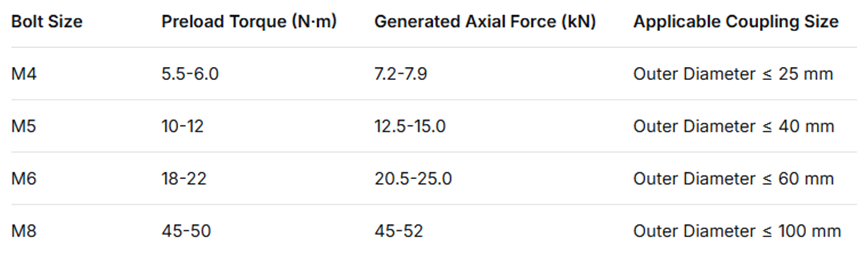
Bolt Pre-tightening: Use a torque wrench to tighten bolts in a diagonal alternating sequence, reaching the final torque value in 2-3 stages.
Final Inspection: Measure axial and radial runout to ensure ≤ 0.02 mm.
Table 2: Recommended Preload Torque for Clamping Type Coupling Bolts
4. Technical Analysis of Set Screw Type Bellows Couplings
4.1 Structural Design Features
Set screw type couplings employ a mechanical locking principle. Radially positioned set screws act directly on the shaft surface, often combined with a parallel key or D-shaped flat to transmit the primary torque (Figure 2). Typical structures include:
Set Screw Array: Usually 2-4 screws, symmetrically arranged at angles of 90° or 120°.
Auxiliary Locking Mechanisms:
Parallel Key + Keyway: Bears the main torque; set screws prevent loosening.
D-Shaped Flat: Single flat surface for simple positioning.
Composite Structure: Combination of key and set screws.
Material Configuration: Screws are typically made of Stainless Steel 304 or Alloy Steel Class 12.9, potentially with nylon/copper locking inserts at the tip.
4.2 Torque Transmission Mechanism and Calculation Model
Torque transmission in set screw type couplings is a composite mechanism:
Key Connection Torque Capacity:
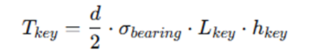
Where
Σbearing is the allowable bearing stress for the keyway (Steel-Steel: 80-120 MPa; Steel-Aluminum: 40-60 MPa).
Set Screw Friction Torque: T
screw=n⋅μf⋅Fs⋅r
Where Fs is the axial force per screw, and
n is the number of screws.
The total torque capacity is the sum of both, but in practice, the key connection typically carries the main load, with set screws primarily serving for axial positioning and anti-loosening.
4.3 Analysis of Performance Characteristics
Economy and Simplicity: Simple structure, manufacturing cost typically 20-35% lower than clamping types.
Compact Design: Smaller radial dimensions, suitable for space-constrained applications.
Quick Installation: No special tools required; lower technical skill needed for installation.
Shaft Adaptability: Lower requirement for shaft surface hardness; can be used with soft shafts or non-precision finished shafts.
High Standardization: Keyway dimensions conform to ISO or ANSI standards, ensuring good interchangeability.
4.4 Installation Requirements and Limitations
Shaft Damage Risk: Set screws directly indent the shaft surface, creating permanent marks that compromise shaft integrity.
Dynamic Imbalance: Asymmetric structure may cause unbalance forces at high speeds, typically limiting speed to ≤5000 rpm.
Poor Repeatable Accuracy: Positioning accuracy degrades after multiple disassemblies/reassemblies, with repeat positioning errors potentially reaching 0.05-0.1 mm.
Loosening Risk: Set screws are prone to loosening in vibratory environments, requiring periodic inspection.
Stress Concentration: Keyway roots create significant stress concentration, reducing fatigue strength by approximately 30-40%.
5. Performance Comparison and Experimental Study
5.1 Comparative Experiment on Torque Transmission Capacity
A comparative test platform was designed to evaluate clamping type and set screw type couplings of identical specifications (outer diameter 32 mm, length 50 mm):
Table 3: Experimental Results Comparing Torque Transmission Performance
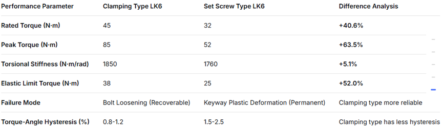
Experimental results show that the clamping type is superior in torque capacity, reliability, and recoverability compared to the set screw type.
5.2 Finite Element Analysis of Dynamic Characteristics
Parametric finite element models for both coupling types were established using ANSYS Workbench for comparative analysis:
Stress Distribution Analysis:
Clamping Type: Stress is uniformly distributed in the tapered contact zone; maximum stress is around bolt holes.
Set Screw Type: Stress is highly concentrated at keyway roots and set screw contact points, with local stress potentially 5-8 times the average value.
Modal Analysis Results:
Clamping Type 1st Torsional Frequency: 1250 Hz
Set Screw Type 1st Torsional Frequency: 1180 Hz
Clamping type dynamic stiffness is 5.9% higher, offering better resonance resistance.
Thermal-Structural Coupling Analysis:
Under a temperature difference ΔT=50°C:
Clamping Type: Thermal stress distribution is uniform; torque change rate: -2.3%.
Set Screw Type: Thermal stress concentration at keyway; torque change rate: -4.8%.
5.3 Long-term Accuracy Retention Test
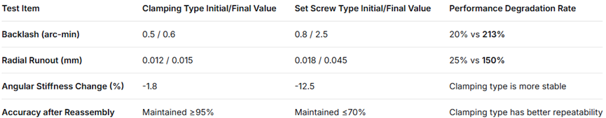
A 1000-hour endurance test simulating real operating conditions (start-stop cycles, variable load, vibration) was conducted:
Table 4: Accuracy Retention Test Results
6. Engineering Applications and Selection Guidelines
6.1 Application Scenario Analysis
Based on performance comparisons, the two coupling types suit different application scenarios:
Applications Favoring Clamping Type:
High-Precision Servo Systems: CNC machine feed axes, robotic joints, optical positioning stages.
High-Speed Transmission: Speeds >3000 rpm, especially ultra-high-speed spindles >10000 rpm.
Frequent Start-Stop or Reversing: Automated production lines, indexing mechanisms, printing machinery.
High-Reliability Requirements: Aerospace, medical equipment, new energy equipment.
Hardened or Precision Shafts: Critical equipment where shaft surface damage must be avoided.
Applications Where Set Screw Type May Be Considered:
Economical Automation Equipment: Packaging machinery, conveyor drives, fans, pumps.
Low-Speed, High-Load: Speeds <500 rpm with steady torque transmission.
Maintenance Convenience Priority: Applications requiring frequent disassembly/replacement.
Extremely Space-Constrained: Insufficient radial space for clamping structure.
Shafts with Existing Keyways: Retrofitting projects where shafts already have machined keyways.
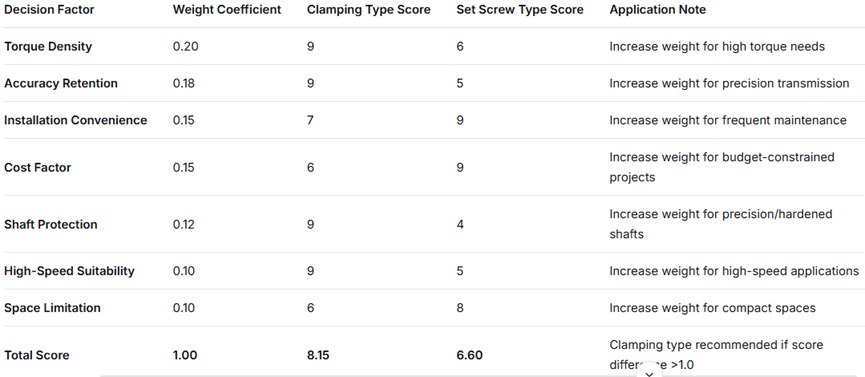
6.2 Selection Decision Model
A multi-factor weighted decision model is established to aid engineering selection:
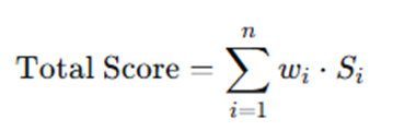
Where wi are weighting factors and Si are individual scores (0-10).
Table 5: Selection Decision Factor Weighting Table (Example)
6.3 Best Practices for Installation and Maintenance
Key Points for Clamping Type Installation:
Use a calibrated torque wrench and apply the manufacturer's recommended preload value.
Follow a diagonal alternating tightening sequence, achieving target torque in stages.
Re-check bolt torque 24 hours after initial operation to compensate for potential stress relaxation.
Regularly inspect protective cover integrity to prevent foreign object ingress into the friction interface.
Key Points for Set Screw Type Installation:
Ensure proper fit between key and keyway, avoiding excessive tightness or looseness.
Set screws should be equipped with reliable locking devices (e.g., nylon inserts, locknuts).
Machine a small locating dimple (depth 0.5-1.0 mm) on the shaft at the screw position to reduce surface damage.
Periodically (e.g., every 500 operating hours) check screw tightness.
7. Technology Trends and Future Outlook
7.1 Material Innovation
Advanced Aluminum Alloys: Use of 7xxx series high-strength aluminum or aluminum matrix composites, increasing strength by 30-50%.
Specialty Stainless Steels: Precipitation-hardening stainless steels (e.g., 17-4PH) provide higher strength and corrosion resistance.
Engineering Ceramic Coatings: Adding DLC (Diamond-Like Carbon) or Al₂O₃ coatings to friction interfaces, increasing friction coefficient to 0.2-0.3.
Shape Memory Alloys: Smart materials enabling self-adjusting clamping force to compensate for temperature or wear changes.
7.2 Structural Optimization Directions
Hybrid Connection Design: Combining advantages of clamping and set screw methods to develop adaptive connection systems.
Modular Design: Quick-change connection modules to adapt to different shaft diameters and conditions.
Integrated Sensors: Built-in sensors for torque, temperature, vibration, enabling condition monitoring and predictive maintenance.
Lightweight Topology Optimization: CAE-based topology optimization reducing weight by 20-30% while maintaining stiffness.
7.3 Concept of Smart Couplings
Next-generation bellows couplings will evolve towards intelligence and adaptability:
Active Clamping Force Control: Piezoelectric ceramics or magnetorheological materials to adjust clamping pressure in real-time.
Wireless Condition Monitoring: Embedded sensors with RF transmission for real-time coupling health monitoring.
Self-Diagnosis and Warning: Big data and machine learning algorithms to predict remaining life and fault risk.
Energy Harvesting Function: Piezoelectric materials to harvest vibrational energy for powering built-in sensors.
8. Conclusion
This paper systematically investigates the two mainstream shaft connection methods for bellows couplings—clamping type and set screw type—through theoretical analysis, numerical simulation, and experimental validation, leading to the following conclusions:
Significant Performance Differences: The clamping type is superior in all aspects including torque capacity (40-60% higher), accuracy retention, repeatable installation precision, shaft protection, and high-speed suitability compared to the set screw type. The set screw type offers cost advantages (20-35% lower) and installation simplicity.
Different Mechanical Mechanisms: The clamping type relies on full-circumference frictional connection with uniform stress distribution. The set screw type depends on localized mechanical locking with significant stress concentration. This is the root cause of the performance difference.
Selection Requires Systematic Consideration: Choice should be based on a comprehensive evaluation of factors including torque requirements, speed range, precision needs, shaft characteristics, cost constraints, and installation conditions. The multi-factor weighted decision model proposed in this paper provides a quantitative basis for selection.
Clear Development Trend: Future bellows couplings will develop towards higher performance, greater intelligence, and higher integration. Material innovation and structural optimization will continue to expand their application boundaries.
Engineering Recommendation: For most precision transmission, high-speed applications, and high-reliability scenarios, the clamping type design is highly recommended. For cost-sensitive, low-speed, light-load applications with lower precision requirements, the set screw type can be considered as an economical solution. As intelligent manufacturing advances, the advantages of clamping type technology will become more pronounced, positioning it as a mainstream choice in the field of precision transmission.
