

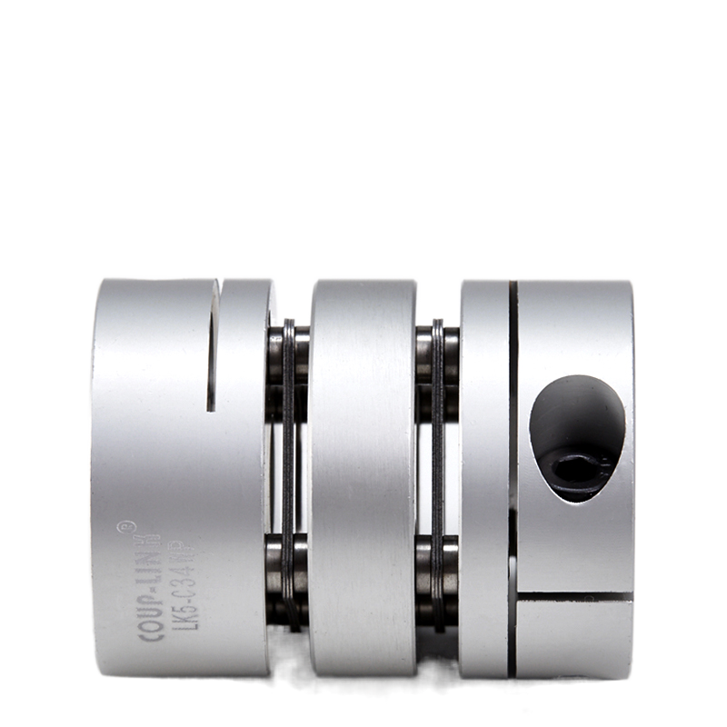
LK5 Series Clamp Type Single/Double Spring Plates
CAUTIONS
1. Be sure to observe allowable tolerances of eccentricity, deflection and axis.
2.Bolts must be tightened with specified torque.
3. The concentricity of the left and right inner diameters of the coupling can be assembled accurately by using special fixtures, In case of strong impact on the coupling, the assembly accuracy may not be maintained and the coupling may be damaged in use,please pay attention to it during operation.4. The use range is - 30*c . 120'c. Despite water and oil resistance, extreme adhesion can also lead to deterioration of the product,avoid this kind of situation.
5. Plate springs consist of thin stainless steel diaphragms, when using, care should be taken to avoid scratches.
6. Do not tighten the clamping bolt before inserting the installation shaft.
INSTALLATION
1.Confirm whether the clamping bolt of the coupling is loose or not, remove rust, dust and oil on the inner diameter surface of the shaft and coupling. in particular, all kinds of greases which have a significant impact on the friction coefficient of the coupling must not have adhesion.
2.Please insert the coupling into the motor shaft. When inserting, do not apply excessive compression and tension force on the elastic components of the coupling, especially when inserting the coupling into the driven shaft after installing the coupling to the motor, excessive compression force may be exerted due to incorrect operation,please note.
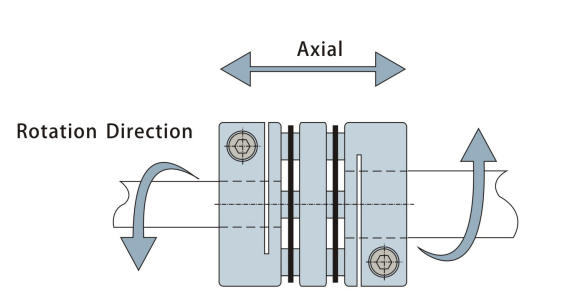
3.when the two clamping bolts are loose, make sure that the coupling can move slightly along the axis and rotation direction. f it can not move smoothly, please readjust the centering of the two axes, This method is recommended a simple method to confirm the left and right concentricity. lf the same method cannot be used, please use other measuring methods to confirm the installation accuracy.
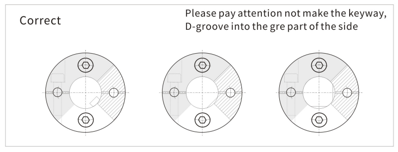
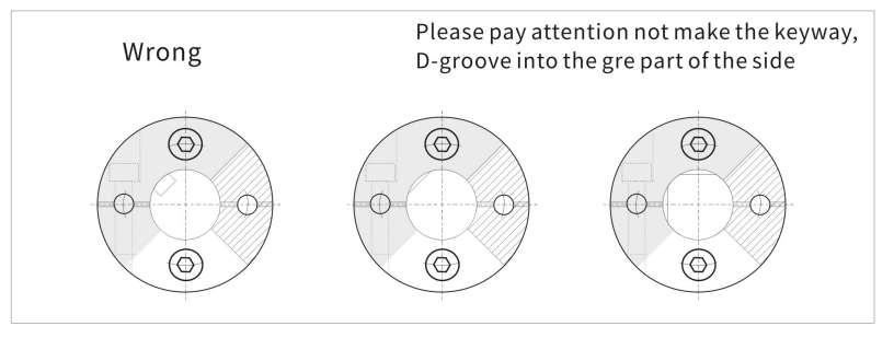
4.Installation shaft is circular in principle. When using non-circular shaft, please pay attention to the installation position shown in the following figure. (Please pay attention not to make the key way, D-groove into the grey part of the side),the improper installation of the shaft may cause damage to the coupling,reduce the shaft clamping force.in order to obtain satisfactory coupling performance, we recommend the use of circular shafts.
RECOMMENDED INSTALLATION METHOD
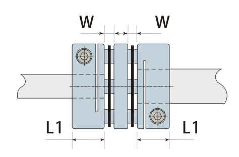
5.The length of the insertion couplings on both sides of the shaft is shown in the figure below, so that the installation shaft runs through the full length of the flange at the side section (L1 size) and does not interfere with the elastic element and the other side of the shaft. Please control the clamping flange face-to-face dimension (W dimension) within the allowable error range of axial displacement relative to the standard value. This value is the allowable value for assuming eccentricity and zero offset angle. Please adjust it as small as possible.
6. Please tighten the two clamping bolts after confirming that there is no compression, tension and other forces in the axial direction, When tightening the bolt, please use the calibrated torsion plate hand and tighten the torque according to the technical parameter table.
7. As an initial anti-loosening measure of clamping bolt, it is suggested that after running for a period of time, the correct tightening torque should be used again for tightening.
