

1.Imbalance Static
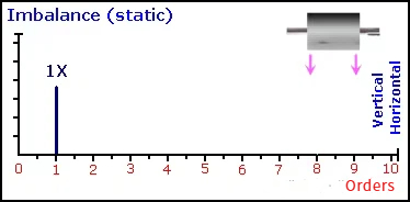
Feature: Radial 1X peak (in the vertical or horizontal direction). If the machine becomes unbalanced, a sinusoidal time-domain waveform with a frequency equal to the rotational speed will appear, showing a prominent peak at the rotational frequency (1X). The simplest model of unbalance is to simplify the center of mass of the rotating shaft to a single point. This type of unbalance is referred to as static unbalance, as it can be detected even when the rotor is not rotating—if placed on frictionless bearings, the center of mass will naturally settle to the lowest position. Static unbalance generates a 1X frequency force on both supporting bearings of the rotor, with the forces acting in the same direction on both bearings. The vibration signals collected from these two bearings are in phase.
2.Imbalance Couple
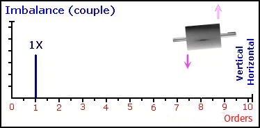
Feature: Radial 1X peak (in the vertical or horizontal direction). If unbalance is present in the machine, a sinusoidal time-domain waveform with a frequency equal to the rotational speed will be generated, resulting in a dominant peak at the rotational frequency (1X) in the spectrum. A rotating body with couple unbalance may be statically balanced (when placed on frictionless bearings, the rotor appears to be perfectly balanced). However, once the rotor begins to rotate, centrifugal forces are generated at its two supporting bearings, and these forces act in opposite directions (i.e., they are out of phase).
3.Imbalance Vertical Machine
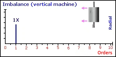
Feature: Radial 1X peak (in the horizontal direction). When measured in the radial (horizontal or tangential) direction, the spectrum will again display a strong peak at the fundamental frequency (1X). To distinguish motor unbalance from pump unbalance, it may be necessary to disassemble the coupling and operate the motor independently while monitoring its 1X spectrum. If the amplitude at 1X remains high, the fault lies with the motor; otherwise, it originates from the pump.
4.Imbalance overhung
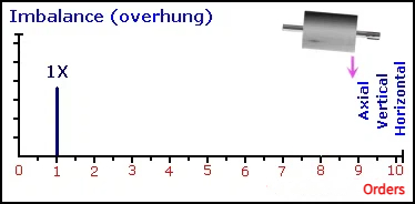
Feature: High-amplitude 1X peaks in both axial and radial directions (vertically or horizontally). In overhung or cantilevered machines, high-amplitude 1X vibration can be detected in the horizontal, vertical, and axial directions. This significant 1X vibration occurs because unbalance induces shaft bending, causing axial displacement of the bearing housing. Common examples of overhung rotors include short-coupled pumps, axial-flow fans, and small turbines. (Phase instability) Note: Distinguish from bearing cocking.
5.Parallel Misalignment
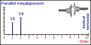
Feature: Radial 2X peak, radial 1X low-amplitude peak (in the vertical or horizontal direction). When the centerlines of the shafts are parallel but not collinear, this condition is termed parallel misalignment (or offset misalignment). Parallel misalignment induces shear stress and bending deformation at the coupling ends of each shaft. Bearings on both sides of the coupling generate high-amplitude 1X and 2X vibrations in the radial direction (vertical and horizontal). In most cases, the amplitude at 2X is higher than at 1X. For pure parallel misalignment, the axial vibration amplitudes at 1X and 2X remain low. Vibrations measured across the coupling are out of phase in the axial and radial directions, with a 180-degree phase difference in the axial direction.
6.Angular Misalignment
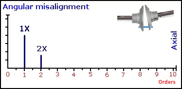
Feature: Axial 1X peak, axial 2X low-amplitude peak, radial 1X low-amplitude peak. When the shafts intersect at a point but are not parallel, this condition is termed angular misalignment. Angular misalignment induces a bending action on the shafts, manifesting as high-amplitude 1X vibration in the spectrum and moderate axial 2X vibration at both bearing locations. Significant radial (horizontal and vertical) 1X and 2X vibrations are also present, but these vibrations are in phase. The vibration exhibits a 180-degree phase difference in the axial direction, while remaining in phase radially.
7.Looseness(Rotating)
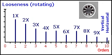
Feature: Radial 1X harmonics (with 0.5X harmonics appearing in severe cases). Excessive clearance between the journal and rolling element bearings (bearing looseness) can generate 1X harmonics, sometimes extending up to 10X. Excessive sliding bearing clearance may produce the aforementioned 0.5X harmonics, commonly referred to as half-order components or subharmonics. These are primarily caused by friction or severe impact forces and can sometimes generate 1/3-order harmonics, often resulting from improper installation of components.
8.Looseness(Structure)
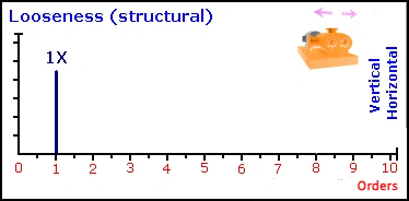
Feature: 1X peak in the horizontal direction. Looseness between the machine and its foundation can cause 1X vibration at structurally weak points, typically in the horizontal direction—though this may vary depending on specific conditions. Severe looseness often generates low-order 1X harmonics. It can be difficult to distinguish between unbalance, foundation looseness, or structural flexibility, especially in vertically mounted machines. If the 1X vibration amplitude in the horizontal direction is significantly greater than that in the vertical direction, looseness is likely the cause. If the horizontal 1X amplitude is smaller than or equal to the vertical 1X amplitude, unbalance is more probable. Foundation looseness or flexibility is typically caused by loose, corroded, or cracked fastening bolts. Note: If the machine foundation is highly flexible, horizontal vibration may be much more pronounced. In such cases, phase analysis can aid identification, with a 180-degree phase difference observed between the machine and foundation in the vertical direction (such vibration, often resulting from loose anchor bolts, baseplates, or grouting, generates 1X frequency vibration).
9.Looseness (Pillow Block)
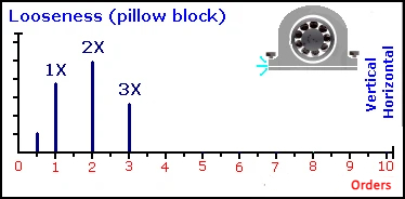
Feature: Radial 1X, 2X, and 3X peaks. The spectrum exhibits vibration components at 1X, 2X, and 3X, typically without other harmonics, though a 0.5X peak may appear in severe cases. Phase analysis is also used to assist in identifying this fault. A 180-degree phase difference exists between the bearing and the foundation.
10.Resonance
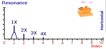
Feature: A "hump" typically appears in the spectrum in only one direction. Resonance is a phenomenon that occurs when the excitation frequency matches the natural frequency of the machine. The natural frequency is the frequency at which a structure vibrates when subjected to an external driving force. In a single axial direction, a high-amplitude peak exists within this "hump." For example, a pump's vane passing frequency may cause a peak at 6X, with increased vibration occurring only in the horizontal direction. If the excitation frequency is increased (or decreased) so that resonance no longer occurs, the amplitude will significantly decrease.
11.Bent Shaft
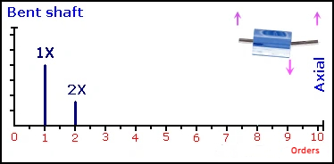
Feature: Axial 1X peak. Shaft bending will induce high-amplitude 1X vibration in the axial direction. If the bend occurs near the center of the shaft, the dominant peak typically appears at 1X; if it is close to the coupling, a 2X peak may also be present. Measurements in the vertical and horizontal axial directions often show 1X and 2X peaks as well, but axial measurement is the most critical indicator here. Phase measurement is highly useful for diagnosing shaft bending faults. The phase difference measured axially at both ends at 1X is 180 degrees (no such difference is observed in the horizontal or vertical directions).
12.Cocked Bearing
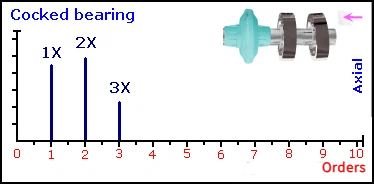
Features: Peaks at 1X, 2X, and 3X frequencies. Cocked bearing, a form of misalignment, generates significant axial vibration. Peaks are typically predominant at 1X, 2X, and 3X. When inspecting suspended pumps or fans, strong axial vibration may be mistaken for misalignment or unbalance. However, peaks at 2X and 3X indicate a higher probability of shaft skew rather than unbalance.
13.Journal Bearing Wear
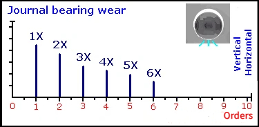
Feature: 1X harmonics. When excessive clearance exists in sleeve bearings, the spectral characteristics closely resemble those of rotational looseness. Pronounced harmonics will appear at 1X, and in most cases, vibration in the vertical axial direction will exceed that in the horizontal direction. In more severe instances, half-order or even one-third-order harmonics may also emerge in the spectrum.
14.Oil Whirl
Feature: Radial 0.38–0.48X peak. During oil whirl, high-amplitude vibration occurs between 0.38X and 0.48X. The peak never appears exactly at 0.5X, but at a slightly lower frequency. Whirl is caused by excessive clearance and light radial loading, which allows the formation of an oil film that induces the journal to vibrate within the bearing at a frequency slightly below 0.5 times the rotational speed.
15.Shaft Rub
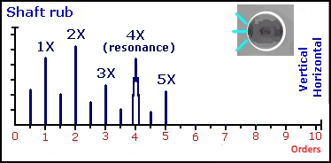
Feature: Radial 1X harmonics (with 0.5X harmonics in severe cases). Rub exhibits spectral characteristics similar to rotational looseness: pronounced 1X harmonics and 0.5X harmonics. Additionally, rub can excite one or more resonances (in the example provided, this occurs at 4X).
16.Eccentricity
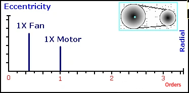
Feature: Radial 1X peaks (in both horizontal and vertical directions). Eccentricity occurs when the center of rotation of a rotating component (such as a gear, bearing, or rotor) deviates from its geometric centerline. An eccentric rotor or bearing will generate high-amplitude radial 1X components, particularly in the direction parallel to the rotor or gear axis. This phenomenon is highly common and closely resembles unbalance.
17.Blade Pass
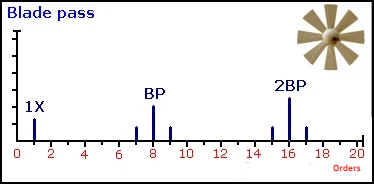
Feature: Peak at blade passing frequency. All pumps, fans, and compressors typically exhibit a peak at their blade passing frequency. The blade passing frequency is equal to the number of blades multiplied by the shaft rotational speed. The peak amplitude may increase if the clearance between blades and the stationary diffuser is uneven. It can also be caused by flow path obstruction.
18.Flow Turbulence
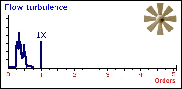
Feature: Random vibration at 50–2000 CPM.Turbulence is caused by variations in air velocity or pressure through fans/blowers, resulting in random low-frequency vibration typically in the range of 50–2000 CPM.
19.Cavitation
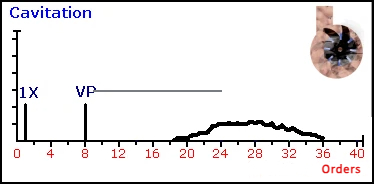
Feature: High-frequency "noise".
Cavitation usually generates random high-frequency vibration or "noise".
A spectral hump is often observed in the frequency spectrum. Cavitation typically occurs due to insufficient Net Positive Suction Head (e.g., low inlet pressure).
It sounds similar to gravel circulating within the pump.
20.Four-stroke Engines
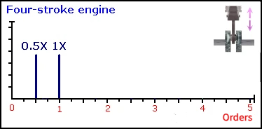
Feature: 0.5X peak for four‑stroke engines; 1X peak for two‑stroke engines.
Reciprocating machinery often exhibits high vibration levels. In four‑stroke engines, which fire every two revolutions, a prominent 0.5X peak is generated. In two‑stroke engines, such as many diesel engines, firing occurs every revolution, producing a dominant 1X peak.
21.Gearbox Analysis
Feature: Peaks at radial 1X/2X. Peaks typically appear at the shaft rotational frequency and gear mesh frequency, though their amplitudes are not high. A 2X peak may be present, accompanied by sidebands of the shaft rotational frequency around the gear mesh frequency. For spur gears, the primary vibration is radial; for helical gears, it is predominantly axial. Time-domain waveform analysis is particularly useful for gearboxes, as it allows visualization of individual pulses corresponding to each tooth engagement. Often, the number of gear teeth can be determined by examining the time-domain waveform. Depending on the fault characteristics, one pulse is observed per revolution of the faulty gear, with the pulses exhibiting varying amplitudes.
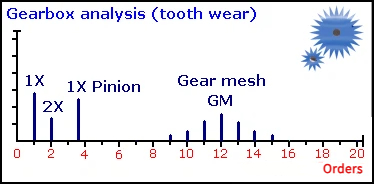
22.Gearbox Analysis(tooth wear)
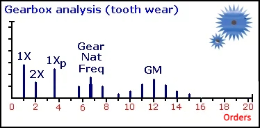
Feature: 1X sidebands around gear mesh frequency
When gear teeth begin to wear, two phenomena occur. First, the amplitude of sidebands around the gear mesh frequency increases, with the sideband spacing equal to the rotational speed of the gear. Second, vibrations at the gear’s natural frequency emerge, which also exhibit sidebands and possess a broad base frequency.
23.Worn Belts
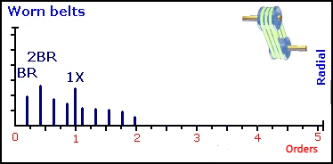
Feature: Sidebands at belt speed frequency
If a belt is worn or loose, peaks and harmonics at the belt speed frequency will be observed. When two pulleys are involved, peaks up to twice the belt speed frequency (2×BR) can be generated. The primary excitation frequency is the "belt frequency" or "fundamental belt-passing frequency"—the frequency at which a fixed point on the belt passes a reference point. This frequency is typically lower than the rotational frequency of either pulley.
24.Eccentricity
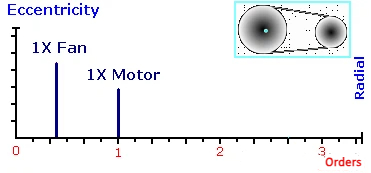
Feature: High-amplitude radial 1X peak.An eccentric pulley produces a strong radial 1X peak, especially in the direction parallel to the belt path. This condition is quite common and resembles unbalance. It can be verified by removing the belt; the same 1X vibration will also be detected on the opposing pulley.
25.Misaligned Sheaves
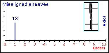
Feature: High-amplitude radial 1X peak
If the natural frequency of the belt coincides with the rotational speed of the drive or driven pulley, belt resonance can cause high vibration amplitudes. The belt’s natural frequency can be adjusted by changing the belt length or altering the belt tension.
