

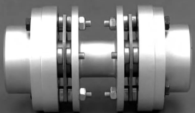
Couplings can be categorized into various types, each exhibiting different characteristics when misaligned. For instance, rigid couplings demonstrate a rotor bending effect, leading to vibration at the line frequency; claw couplings may exhibit vibrations at frequencies corresponding to the number of claws; and gear couplings might display gear meshing frequencies, among other symptoms.
In field applications, misalignment in diaphragm couplings and flexible elastomer couplings typically manifests as vibrations at 1x and 2x rotational frequencies. In some cases, the 2x rotational frequency may be predominant, while in others, the 1x rotational frequency dominates significantly. This depends on the form of misalignment and the measurement location.
Understanding the type of coupling is essential, as is familiarity with the equipment structure. Different equipment configurations exhibit distinct vibration behaviors under misalignment conditions. For instance, in sleeve bearings, the larger clearance may compensate for misalignment, often preventing noticeable vibration. However, this does not negate the potential for bushing wear, which may eventually manifest through other vibration patterns. Ultimately, the root cause may still be coupling misalignment.
The following section outlines diagnostic approaches specifically for misalignment in diaphragm and flexible elastomer couplings.
I. Visual Inspection and Testing
1. Both types of couplings exhibit strong vibration compensation capabilities. Within certain misalignment tolerances, vibrations may not be prominently observable. However, symptoms such as diaphragm deformation or fracture in diaphragm couplings, or wear in elastomer couplings, may occur. In severe cases, debris from elastomer components may be found on the ground. If any of these signs are detected, realignment should be performed—regardless of whether misalignment is the root cause of the vibration.
2. Misalignment can arise from multiple factors, one of which is structural loosening. Loose foundation bolts typically induce 1x rotational frequency vibration. However, if the loosening severity affects alignment, 2x rotational frequency vibration may emerge. Any looseness should be corrected first.
3. According to Newton’s third law, every force has an equal and opposite reaction. Thus, bearings on both sides of the coupling tend to show the most significant vibration responses under misalignment. Due to potential stiffness disparities between the two sides, the bearing on the less rigid side often exhibits noticeably higher vibration amplitudes, while the stiffer side may show minimal vibration.
4. In large units equipped with sleeve bearings, radial misalignment often leads to lower oil film pressure and temperature in the bearing at a lower position (with a elevated journal), compared to the bearing at a higher position (with a lowered journal).
5. For machinery with rolling element bearings, if significantly high vertical vibration is observed only on the bearing housing adjacent to the coupling—and provided that foundation or connection looseness has been ruled out—angular misalignment (vertical offset) of the coupling should be considered.
6. Thermally induced misalignment often manifests as follows: vibration levels are acceptable upon startup, gradually increase during operation, and eventually stabilize at a higher value. The amplitude of vibration depends on the degree of misalignment caused by thermal expansion.
II. Vibration Spectrum and Time-Domain Waveform
In vibration diagnostics, spectrum analysis alone often presents uncertainty. A conclusive diagnosis should integrate observations across vibration location, direction, temperature, load, rotational speed, and other operational parameters. The following describes typical spectral and waveform patterns.
Misalignment-induced vibrations typically occur at 1x, 2x, and sometimes 3x rotational frequencies. Depending on the severity and type of misalignment, these frequency components may appear in various combinations.
Angular misalignment typically generates predominant 1x vibration.
Parallel offset misalignment mainly produces 2x vibration.
Combined misalignment may result in both 1x and 2x vibrations, and occasionally 3x components as well.
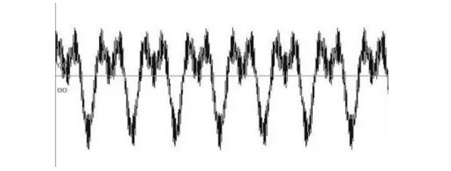
In time-domain waveforms, the relative phase between 1x and 2x vibrations determines the waveform shape, often exhibiting "M" shape (‑180°) or "W" shape (0° or 180°) patterns. For spectral measurements, data should be collected in Horizontal (H), Vertical (V), and Axial (A) directions. Different misalignment types manifest distinct spectral characteristics across these directions.
Below are typical spectrum and waveform presentations for coupling misalignment:
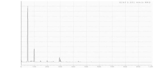
1.Typical Spectrum for Pure Radial Misalignment
For pure radial misalignment, both 1x and 2x vibration amplitudes are relatively low in the axial direction.
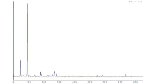
2.Typical Spectrum for Axial Misalignment
The spectrum displays high 1x vibration amplitude with relatively lower 2x component.
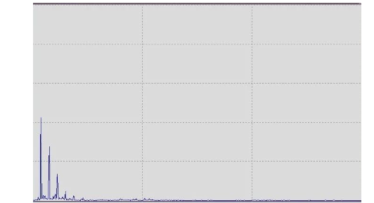
3.Spectrum with Combined Radial and Axial Misalignment
4.Waveform with Phase Difference of –180° or 0°/180° Between 1x and 2x
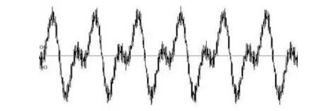
5.Waveform with 90° Phase Difference Between 1x and 2x
III. Phase Analysis
The most effective method for diagnosing misalignment is phase analysis across the coupling. A phase difference close to 180° (±40°–50°) between both sides of the coupling strongly indicates misalignment. The severity of misalignment correlates with how closely the phase difference approaches 180°.
For accurate diagnosis, compare phase differences in horizontal, vertical, and axial directions on both sides of the coupling. If the shafts are well-aligned horizontally but misaligned vertically, a significant phase difference will be observed in the vertical direction.
In cases of coupling misalignment, the radial phase difference between the two bearings supporting the rotor on either side of the coupling tends to be near 0° or 180° (±30°).
When comparing horizontal and vertical phase differences, most misalignment cases exhibit a phase difference close to 180° between these two directions. This helps distinguish misalignment from unbalance faults.
Phase changes can also indicate real-time alignment variations. For rotors with thermal compensation, a transition from misalignment (at room temperature) to alignment (at operating temperature) may occur, reflected in a phase shift from ~180° to ~0° across the coupling.
Compare phases in the vertical, horizontal, and axial directions at each bearing. If the phases on both sides of the coupling are similar, alignment is good. A 180° phase difference radially with in-phase axially suggests parallel offset misalignment.
In most practical cases, misalignment is a combination of radial and axial deviations. Regardless of the measurement direction, a phase difference approaching 180° indicates a higher probability of misalignment.
