
1. Introduction
In the drive trains of high-end equipment such as precision CNC machine tools, industrial robots, semiconductor manufacturing equipment, and precision measuring instruments, there are extreme requirements for the accuracy, real-time performance, and synchronization of motion transmission. In such systems, the coupling must not only transmit torque but, more critically, must achieve error-free angular displacement synchronization between the input and output shafts—i.e., Zero Backlash and Phase Lag-Free transmission.
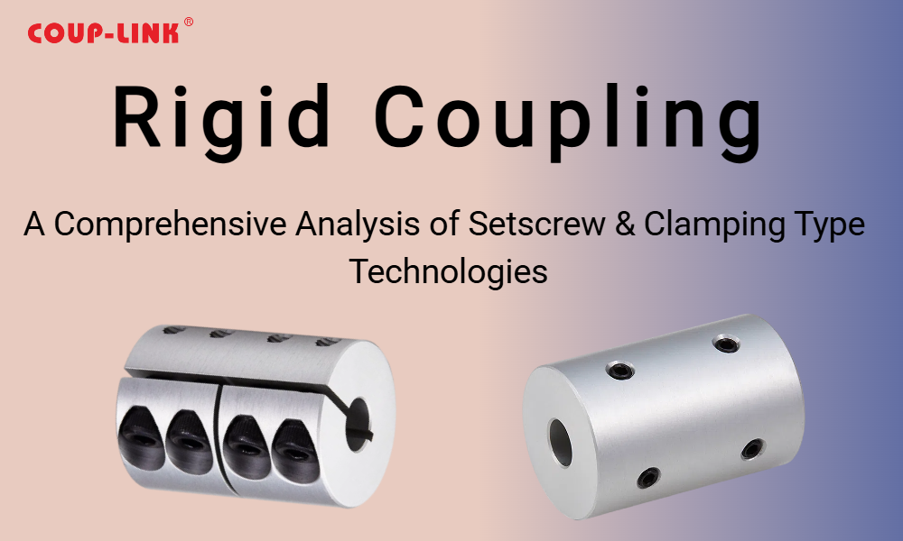
The rigid coupling, which connects two shafts via a single, inflexible body with no flexible elements, is the ideal choice for this purpose, structurally eliminating transmission errors caused by elastic deformation or mechanical clearance. However, the limiting factor of its performance is determined not solely by the coupling body itself, but more critically by the quality of its connection to the drive shafts. The setscrew (which transmits torque via friction generated by axial clamping force) and the clamping screw (which transmits torque via friction generated by uniform surface pressure from radial contraction) are the two core shaft connection technologies. The choice between them directly affects drive reliability, precision retention, and maintenance costs. This paper provides a comparative study and engineering analysis of these two technologies.
2. Structure and Fixation Principles of Rigid Couplings
2.1 Basic Structure
Rigid couplings are typically single-piece machined components. Common types include:
Sleeve Coupling: The simplest form, consisting of a hollow sleeve.
Flanged Rigid Coupling: Comprises two hubs with flanges and a set of connecting bolts. Bolt preload forces the flange faces into tight contact, transmitting torque and maintaining alignment simultaneously.
Split Coupling: Split axially and clamped around the shaft by bolts tightening the outer shell.
2.2 Setscrew Fixation Principle
A radial threaded hole is machined into the coupling hub, into which a case-hardened setscrew is inserted.
The tip of the screw bears directly against the surface of the transmission shaft. The axial preload force F_a of the screw creates a normal force N on the shaft surface, which in turn generates a frictional force F_f = μ * N to transmit torque.
The torque transmission capacity T_ss is given by: T_ss = (μ * F_a * d) / (2 * k), where d is the shaft diameter and k is a safety factor.
A flat or a dimple is often machined onto the shaft surface for the screw tip to engage, preventing axial creep.
2.3 Clamping Screw Fixation Principle
The coupling hub is typically designed with a slitted or split structure.
Circumferentially distributed clamping screws (usually two or more) are tightened, causing the slitted portion of the hub to elastically contract uniformly. This applies a uniform 360° radial pressure p on the shaft surface.
The resulting significant frictional torque transmits the load. The torque capacity T_clamp is given by: T_clamp = (μ * p * π * d * L) * (d/2), where L is the contact length.
This constitutes a keyless, point-contact-free full-friction connection.
3. Core Advantages and Application Fields
3.1Core Advantages
1.Absolute Zero Backlash and Ultra-High Torsional Stiffness: The rigid connection ensures no mechanical backlash or elastic hysteresis, providing excellent phase synchronization and the fastest dynamic response.
2.High Alignment Accuracy: When paired with precision-machined, high-tolerance shafts and holes, near-perfect concentricity can be achieved, ensuring smooth transmission.
3.Simple Structure, Low Cost: Simpler construction and lower manufacturing cost compared to flexible couplings (especially the setscrew type).
4.Maintenance-Free: No flexible elements requiring lubrication or replacement.
3.2 Application Fields
Rigid couplings are suitable for applications with extremely high shaft alignment accuracy and no relative displacement:
Precision Positioning Systems: Wafer stage drives in lithography machines, lead screw drives in measuring machines.
High-Speed Spindle Systems: Connection between motor spindles and tools in internal grinders, high-speed milling spindles.
Multi-Axis Drives with Extreme Synchronization Requirements: Plate cylinder drives in printing machinery, roller drives in textile machinery.
Low-Speed, Heavy-Duty, Well-Aligned Drives: Connections between gearboxes and rolls in some large rolling mills.
4. Comparative Analysis of the Two Fixation Methods and Usage Considerations
4.1 Setscrew Fixation
Advantages:
Extremely simple structure, lowest cost.
Easy installation, no special tools required.
Disadvantages and Considerations:
1.Severe Stress Concentration: The point contact of the screw tip on the shaft surface creates very high localized contact stress, significantly reducing the fatigue strength of the shaft and creating a potential origin for fracture. Prohibited for applications subject to high-cycle fatigue loads.
2.Limited Torque Transmission Capacity: Relies solely on friction at one or multiple points; torque capacity is relatively low and susceptible to loosening under vibration.
3.Irreversible Shaft Damage: The screw creates an indentation (brinelling) on the shaft surface. The shaft often requires re-machining or must be scrapped after disassembly.
4.Effect on Dynamic Balance: The screw and indentation disrupt the initial dynamic balance of the system, potentially causing vibration at high speeds.
5.Locking Requirement: High-strength screws must be used in conjunction with thread-locking fluid (e.g., Loctite). Torque must be checked periodically after installation.
4.2 Clamping Screw Fixation
Advantages:
1.No Stress Concentration: Uniform radial pressure avoids any point contact, causes no damage to the shaft, and preserves its integrity and fatigue strength.
2.High Torque Transmission Capacity: The total frictional force generated by the large contact area far exceeds that of the setscrew method, offering higher reliability.
3.Excellent Centering Ability: The contraction deformation aids self-centering, improving alignment accuracy.
4.Ease of Repeated Assembly/Disassembly: Loosening the screws allows the coupling to be removed, causing no damage to either the shaft or the coupling itself.
5.Good Dynamic Balanceability: The symmetrical clamping structure is less likely to disrupt dynamic balance, making it more suitable for high-speed applications.
Disadvantages and Considerations:
1.Higher Cost: Structure is more complex than setscrew type, leading to higher manufacturing cost.
2.Higher Installation Requirements: A torque wrench must be used to tighten the clamping screws in a specified sequence and with specified torque values, in a crossed and stepped pattern, to ensure uniform pressure.
3.Stringent Bore Tolerance Requirements: The fit tolerance with the shaft (typically H7/js6) is critical to ensure sufficient contact area and contraction量 (contraction amount).
4.Shaft-Hub Contact Surface Requirements: The fitting surfaces of the shaft and hub bore must have low roughness (typically Ra < 1.6 μm) and must be absolutely clean and free of oil to ensure a stable coefficient of friction.
4.3 General Considerations
1.Extremely High Alignment Requirements: Rigid couplings cannot compensate for any form of installation error (radial, angular, axial). Even minor misalignment will generate significant additional bending moments and stresses within the system, leading to premature failure of shafts, bearings, and the coupling itself. Precision alignment tools like laser alignment systems must be used during installation, with residual errors controlled within 0.05 mm.
2.Thermal Expansion Considerations: Differential thermal expansion between the shaft and coupling due to operational temperature differences must be accounted for in material selection and fit tolerance to avoid connection failure or seizure due to changes in interference.
3.Safety Factor: Given their lack of compensation ability, a larger safety factor (typically 3-5 times the calculated torque) must be applied during selection to account for unforeseen additional loads.
5.Conclusion and Outlook
Rigid couplings are the cornerstone of ultra-precise, high-stiffness drives. The choice between setscrew and clamping screw fixation methods embodies the eternal engineering trade-off between cost and performance.
Setscrew fixation is suitable for low-torque, low-speed, low-cycle applications where cost is extremely sensitive. However, its inherent shaft damage and potential reliability risks are leading to its diminishing use in modern high-end equipment.
Clamping screw fixation, despite a higher initial cost, offers advantages of non-damage, high torque capacity, high reliability, and ease of maintenance, making it the preferred solution for the vast majority of industrial applications, particularly in medium-to-high speed and high-precision fields.
For the drive system designer, a deep understanding of the mechanical fundamentals and failure modes of these two technologies is key to making the correct choice. In the future, advancements in materials science and manufacturing processes (e.g., carbon fiber composite couplings, intelligent clamping force monitoring systems) will push rigid couplings towards further lightweighting, higher speed capability, and greater intelligence, continuing to support the performance limits of high-end equipment.