
1. What is a coupling?
A mechanical device that connects two shafts or a shaft and a rotating component to transmit torque and motion while rotating together without disconnecting.
2. How many major types of couplings are there?
There are three major types: rigid couplings, flexible couplings, and safety couplings.
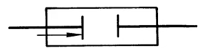
3. How to draw the simplified diagram symbol of a coupling?

4. What is a rigid coupling?
A coupling that cannot compensate for relative displacement between two shafts.
5. How many types of rigid couplings are there?
There are flange couplings, radial key flange couplings, sleeve couplings, clamp couplings, and parallel shaft couplings.
6. How is the simplified diagram symbol for a rigid coupling drawn?
7.What are the characteristics of a rigid coupling?
A rigid coupling does not have the ability to compensate for relative misalignment between the two connected shafts, nor does it have cushioning or vibration-damping properties; however, it has a simple structure and is cost-effective. A rigid coupling should only be selected when the load is stable, the speed is constant, and the relative misalignment between the two connected shafts can be kept to an extremely small degree.
8. What is a flange coupling?
A coupling that connects two shafts by bolting the flanges of the two coupling halves together.
9.What are the characteristics of a flange coupling?
Simple structure, reliable operation, easy to install and disassemble, good rigidity, high torque transmission capacity, but cannot absorb shocks. When the alignment accuracy of the two shafts is low, it will cause significant additional loads. It is suitable for general transmission with smooth operation, but requires high alignment and manufacturing accuracy for high-speed transmission.
10. What is a radial key flange coupling?
Answer: A coupling that connects the two halves of the coupling using radial keys and ordinary bolts.
11. What is a sleeve coupling?
A coupling that connects two shafts in a certain way using a common sleeve.
12. What are the characteristics of a sleeve coupling?
It has a simple structure, is easy to manufacture, has a small radial dimension, and is low in cost. However, it requires a significant axial movement during installation and removal, and can only be used to connect two cylindrical shaft extensions with the same diameter. It is generally used in small-power transmission systems with smooth operation.
13. What is a clamp-type coupling?
A coupling that uses two axially split clamps to clamp the shafts together in a certain way to achieve connection between two shafts.
14. What are the characteristics of a clamp-type coupling?
Easy to install and remove without needing to move the two shafts axially, but difficult to balance, and the two shaft diameters must be identical cylindrical shapes. Suitable only for low-speed horizontal or vertical shaft systems, and best suited for transmitting smooth loads.
15. What is a parallel shaft coupling?
A coupling that connects two parallel shafts using an intermediate disc and pins.
16. What is a flexible coupling?
A coupling that can compensate for relative displacement between two shafts.
17. How many subcategories are there for flexible couplings?
There are two subcategories: flexible couplings without elastic elements and flexible couplings with elastic elements. Examples include chain couplings, sliding block couplings, and elastic couplings.
18. How is the simplified diagram symbol for a flexible coupling drawn?
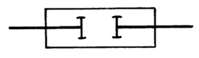
19. What is a flexible coupling without elastic elements?
A flexible coupling without elastic connecting elements.
20. What are the characteristics of a flexible coupling without elastic elements?
A flexible coupling without elastic elements not only transmits motion and torque but also has varying degrees of axial, radial, and angular compensation performance. They have high load-carrying capacity but lack cushioning and vibration-damping properties. At high speeds, unstable speeds, or frequent forward/reverse operations, they may produce impact noise. They are suitable for low-speed, heavy-load, and stable-speed applications.
21. Into how many categories are flexible couplings without elastic elements divided?
They are divided into universal couplings; cross-shaft universal couplings; toothed couplings; chain couplings; and sliding block couplings, etc.
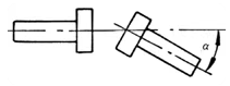
22. What is a universal joint coupling?
A coupling that allows torque transmission under significant angular displacement.
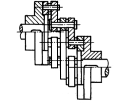
23. What is a cross-shaft universal joint coupling?
A universal joint coupling that uses a cross-shaft intermediate component to connect two shafts with different axis lines.
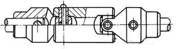
24. What are the characteristics of a cross-axis universal joint coupling?
It has a compact radial outer dimension, is easy to maintain, has high transmission efficiency, a long service life, low noise, and can transmit power between two intersecting axes in space. The angle between the two axes can be large. However, when using a single universal joint coupling, the speed of the driven shaft exhibits periodic fluctuations. It is primarily used for power transmission connections between intersecting axes.
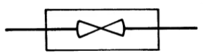
25. How is the simplified diagram symbol for a universal joint drawn?
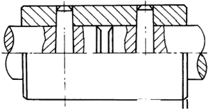
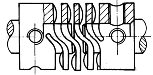
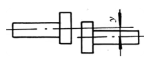
26. What is a gear coupling?
A coupling that uses internal and external teeth to connect two coupling halves.
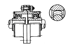
27. What are the characteristics of a gear coupling?
They have high load-carrying capacity, excellent compensation for relative displacement between two shafts, and reliable operation. However, they are difficult to manufacture and require proper lubrication during operation. They are suitable for drive shaft systems with frequent starts and reversals. The TGL type has cushioning and vibration-damping properties and is suitable for medium and small power transmission. The GⅡCL and GⅡCLZ types have higher torque transmission capacity but inferior compensation performance compared to the GICL and GICLZ types, which are more widely used. The GICLZ and GⅡCLZ types require an intermediate shaft to increase radial and angular displacement.
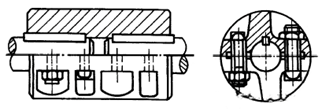
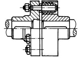
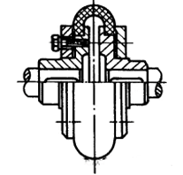
28. What is a chain coupling?
A coupling that uses a common chain to engage with two parallel sprockets of the same tooth count to connect two half couplings.
![]()
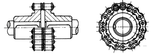
29. What are the characteristics of a chain coupling?
It has a simple structure, uses standard components, has good manufacturability, is easy to manufacture, does not require high installation accuracy, has a certain degree of compensation capability, is suitable for a wide range of environmental conditions, but has poor vibration absorption and cushioning performance, and poor safety. It can be used in general horizontal drive shaft systems for continuous operation.
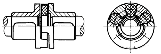
30. What is a sliding block coupling?
A coupling that connects two half couplings by allowing an intermediate sliding block to move within corresponding radial grooves on the end faces of the two half couplings.
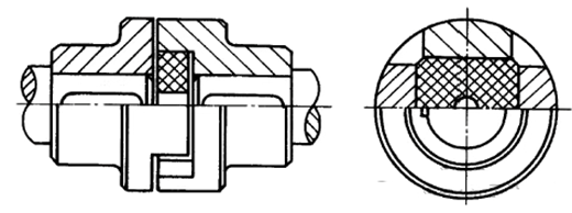
31. What are the characteristics of a sliding block coupling?
It has a simple structure, compact radial dimensions, and allows for significant radial displacement between the two shafts. The nylon sliding blocks also provide some vibration damping and cushioning, but they are sensitive to angular displacement and have low transmission efficiency. They are primarily used for connecting two shafts with significant radial displacement. The operating temperature range for nylon sliding blocks is -20°C to 70°C.
32. What is an elastic element flexible coupling?
A flexible coupling that uses the elastic deformation of elastic elements to compensate for relative displacement between two shafts, mitigate impact, and absorb vibrations.
33. What are the characteristics of flexible couplings with elastic elements?
Flexible couplings with elastic elements can transmit motion and torque; they have varying degrees of axial, radial, and angular compensation performance; they also have varying degrees of vibration reduction and cushioning effects, improving the working performance of the transmission system.
34. How many types of flexible couplings with elastic elements are there?
They are divided into two categories: metal elastic element flexible couplings and non-metal elastic element flexible couplings.
35. What is a metal elastic element flexible coupling?
A flexible coupling with metal elastic elements.
36. How many types of metal elastic element flexible couplings are there?
They are divided into diaphragm couplings, bellows couplings, elastic tube couplings, etc.
37. What are the characteristics of a metal elastic element flexible coupling?
In addition to having good cushioning and vibration damping performance, metal elastic element flexible couplings have a large load-bearing capacity and are suitable for applications with large variations in speed and load, as well as high-temperature or low-temperature environments.
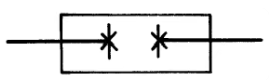
38. How is the simplified diagram symbol for a flexible coupling drawn?
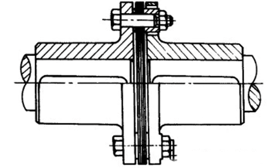
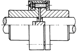
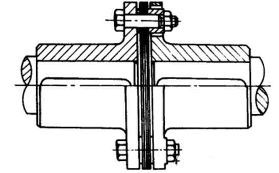
39. What is a diaphragm coupling?
Answer: A coupling that uses spring plates connected to two coupling halves by bolts or other means.
40. How many types are diaphragm couplings classified into?
They are classified into:
Diaphragm Couplings (Lightweight Aluminum Alloy Single-Diaphragm);
Diaphragm Couplings (Lightweight Aluminum Alloy Double-Diaphragm);
Diaphragm Couplings (Lightweight Aluminum Alloy);
Diaphragm Couplings (Aluminum Alloy);
Steel Diaphragm Couplings (Single/Double-Diaphragm), etc.
41. What are the characteristics of the lightweight aluminum alloy single diaphragm coupling?
Featuring zero backlash and synchronous operation, it is specifically designed for high-precision applications such as servo motors, stepping motors, and encoders. It offers high rigidity while accommodating significant installation misalignment. Constructed with specially treated aluminum alloy for reduced inertia, it employs a clamping-type connection and is available in metric or imperial bore sizes. Torque range: 0.5 Nm to 500 Nm.
42.What are the characteristics of the lightweight aluminum alloy double-diaphragm coupling?
Featuring zero backlash and synchronous operation, this specialized component is engineered for high-precision applications including servo motors, stepping motors, and encoders. It demonstrates superior rigidity while providing double the misalignment absorption capacity compared to single-diaphragm couplings. Fabricated from specially treated aluminum alloy, it achieves minimized rotational inertia. Incorporates clamping-type connections with optional metric or imperial bore sizes. Torque capacity: 0.5 Nm to 500 Nm.
43. What are the characteristics of the lightweight aluminum alloy diaphragm coupling?
Featuring zero backlash and synchronous operation, it is engineered for high-precision applications such as servo motors, stepping motors, and encoders. The coupling demonstrates high rigidity with enhanced capacity to absorb installation misalignment, available in both single-diaphragm and double-diaphragm configurations. Constructed with specially treated lightweight aluminum alloy, it achieves reduced rotational inertia. Utilizes a clamping-type connection with metric or imperial bore size options. Torque range: 0.5 Nm to 500 Nm.
44. What are the characteristics of the aluminum alloy diaphragm coupling?
Designed for zero-backlash synchronous operation in precision motion systems, this variant is optimized for servo/stepping motors and encoder integration. It combines high torsional stiffness with substantial misalignment compensation, supporting both single- and double-diaphragm architectures. Fabricated from high-grade aluminum alloy, it delivers low inertia characteristics. Features a clamping-style interface adaptable to metric or imperial shaft dimensions. Operational torque: 0.5 Nm to 500 Nm.
45. What are the characteristics of the steel diaphragm coupling (single/double-diaphragm)?
Engineered for heavy-duty industrial applications, this coupling excels in high-torque transmission (5 Nm to 30,000 Nm) with exceptional rigidity and dynamic balancing precision. Complies with international explosion-proof certifications (e.g., European ATEX and Japanese Industrial Standards). Widely deployed in industrial pumps, printing machinery, papermaking equipment, compressors, and generators. Offers flexible mounting via taper bush connections or keyway joints, compatible with metric/imperial shaft sizing.
46. What is a bellows coupling?
A coupling that uses bellows connected by welding or other means to connect two half couplings.
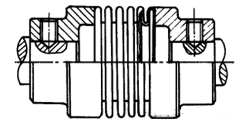
47. What are the characteristics of a bellows coupling?
No backlash, specifically designed for high-precision transmission applications such as servo motors, stepper motors, and encoders. It features torsional rigidity. It can withstand high temperatures (up to 280°C) and has anti-corrosion properties. It can be connected via clamping or expansion sleeves, with metric or imperial diameter sizes. Torque range: 0.5 Nm to 500 Nm.
48. What is an elastic tube coupling?
A coupling that uses an elastic tube to connect two shafts.
49. What are the characteristics of an elastic tube coupling?
No backlash, specifically designed for high-precision transmission applications such as servo motors, stepper motors, and encoders. Features torsional rigidity, low inertia, and exceptional sensitivity. Rotational characteristics are identical in both clockwise and counterclockwise directions. Clamping-type connection with metric or imperial diameter holes. Torque range: 0.5 Nm to 100 Nm.
50. What is a non-metallic elastic element flexible coupling?
A flexible coupling with non-metallic elastic elements.
51. How many types of non-metallic elastic element flexible couplings are there?
They are divided into flower-shaped flexible couplings, elastic sleeve pin couplings, elastic pin couplings, and tyre-type couplings, etc.
52. What are the characteristics of non-metallic elastic element flexible couplings?
Non-metallic elastic element flexible couplings have excellent cushioning and vibration damping performance when the rotational speed is unstable; however, due to the low strength, short service life, limited load-bearing capacity, and inability to withstand high or low temperatures of non-metallic (rubber, nylon, etc.) elastic elements, they are suitable for high-speed, light-load, and ambient-temperature applications.
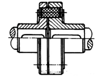
53. What is a flower-shaped elastic coupling?
A coupling that uses flower-shaped elastic elements placed between the protruding claws of the two coupling halves to connect them.
54. What are the characteristics of a flower-shaped elastic coupling?
Torsional elasticity, vibration absorption, maintenance-free, compact design, and low inertia. It is available in two structural forms: cast material and steel material. Steel material is most suitable for high-load drive units, such as rolling mills, elevators, and spline shaft sleeves. Torque range: 5 Nm to 35,000 Nm.
55. What is an elastic sleeve pin coupling?
A coupling that connects two halves by installing pins with elastic sleeves at one end into the flange holes of the two coupling halves.
56. What are the characteristics of an elastic sleeve pin coupling?
It has a compact structure, is easy to assemble, and possesses certain elasticity and cushioning properties. It can compensate for relatively small relative displacements between two shafts. However, when the displacement is too large, the elastic components are prone to damage. It is primarily used in general-purpose medium and small-power transmission shaft systems, with an operating temperature range of -20°C to 70°C.
57. What is an elastic pin coupling?
A coupling that uses several pins made of non-metallic materials placed in the flange holes of the two coupling halves to connect them.
58. What are the characteristics of a flexible pin coupling?
Simple structure, easy to manufacture, convenient to replace, and the pins are wear-resistant. However, it has poor elasticity and cannot compensate for large relative displacements between the two shafts. It is primarily used in drive shaft systems with relatively stable loads, frequent starts, significant axial movement, and low requirements for cushioning. The operating temperature range is -20°C to 70°C.
59. What is a tyre-type coupling?
A coupling that uses tyre-shaped elastic elements connected to the two halves of the coupling with bolts.
60. What are the characteristics of a tire-type coupling?
Simple structure, good elasticity, low torsional stiffness, strong vibration damping capability, and ability to compensate for large relative displacement between two shafts. However, it has limited radial load capacity. It is primarily used in drive shaft systems with significant impact loads, frequent direction changes, and frequent starts, operating at ambient temperatures of -20°C to 80°C.
61. What is a safety coupling?
A coupling with overload safety protection functionality.
62. How many types of safety couplings are there?
They are divided into pin-type: LF-type elastic pin couplings; friction-type: MAL friction safety couplings and AMN internal friction couplings; magnetic powder-type, centrifugal-type, hydraulic-type, etc.
63. What are the characteristics of a safety coupling?
Transmits motion and torque, provides overload safety protection. Flexible safety couplings also have varying degrees of compensating performance.
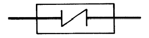
64. How is the simplified diagram symbol for a safety coupling drawn?
65. What is theoretical torque T?
The stable torque transmitted by the coupling when the actual operating conditions are not taken into account.
66. What is nominal torque Tn?
The torque that each specification of coupling can transmit over the long term, designed according to series requirements.
67. What is calculated torque Tc?
The torque that takes into account the effects of actual operating conditions and serves as the basis for selecting or calculating the coupling.
68. What is the permissible torque [T]?
The torque that can be transmitted continuously based on the strength or deformation limits of the weakest component in the coupling.
69. What is the maximum torque Tmax?
The maximum torque transmitted by the coupling due to instantaneous overload.
70. What is the permissible maximum torque [Tmax]?
The permissible value of the maximum torque for the coupling.
71. What is the alternating fatigue torque Tk?
The torque that the couplings under long-term periodic cyclic variations.
72. What is the impact torque Ts?
The instantaneous maximum torque generated during startup or speed changes.
73. What is the excitation torque Ti?
The torque generated when producing periodic amplitude.
74. What is the permissible speed [n]?
The speed permitted for use based on restrictions such as the working stability and strength of the coupling.
75. What is the operating condition coefficient K?
The ratio of the calculated torque of the coupling to the theoretical torque, influenced by factors such as changes in the load on the drive shaft system and the working environment.
76. What is the power source coefficient Kw?
The additional load coefficient caused by differences in power source categories.
77. What is the starting coefficient Kz?
The additional load coefficient caused by starting frequency.
78. What is the temperature coefficient Kt?
The strength reduction coefficient of non-metallic elastic element materials under temperature influence.
79. What is the frequency coefficient Kf?
The coefficient caused by the influence of alternating fatigue torque frequency.
80. What is the amplification coefficient Kv?
The coefficient considered when using elastic couplings in vibration systems to account for increased impact torque.
81. What is the impact coefficient Ks?
The coefficient caused by increased impact torque.
82. What is the mass coefficient Kj?
The mass distribution coefficient during impact and vibration.
83. What is the permissible radial compensation amount [△Y]?
The permissible radial relative displacement between the two shafts connected by the coupling at specified locations.
84. What is the permissible axial compensation amount [△X]?
The permissible axial relative displacement between the two shafts connected by the coupling at the ends.
85. What is the permissible angular compensation amount [△a]?
The permissible angular relative displacement between the two shafts connected by the coupling.
86. What is static stiffness Cs?
The stiffness of the coupling under static load.
87. What is dynamic stiffness Cd?
The stiffness of the coupling under dynamic load.
88. What is the torsional stiffness C?
The torque required per unit angle of rotation between the two halves of the coupling.
89. What is the radial stiffness Cy?
The force required to produce a unit deformation in the radial direction between the two halves of the coupling.
90. What is the axial stiffness Cx?
The force required to produce a unit deformation in the axial direction between the two halves of the coupling.
91. What is the permissible torsional angle [φ]?
The angle of relative torsion between the two halves of the coupling under the action of the permissible torque.
92. What is the maximum torsional angle φmax?
The angle of relative torsion between the two halves of the coupling under the action of the maximum torque for a short period of time.
93. What factors should be considered when selecting a coupling?
The mechanical characteristics of the power source; alignment capability; load category; permissible speed of the coupling; and operating environment.
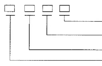
94. What components make up the model number of a coupling?
The model number of a coupling consists of a group code, type code, structural form code, and specification code.
95. How is the model number of a coupling represented?
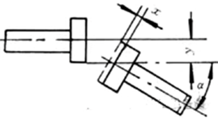
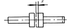
96. What are the types of shaft deviation?
There are four types of shaft deviation: axial deviation, angular deviation, radial deviation, and combined deviation.
97. What is axial deviation?
Axial deviation refers to the deviation caused by mechanical reasons resulting in reciprocating micro-movements between shafts.
98. What is angular deviation?
During installation, when the centre lines of two shafts form an angle, the resulting deviation is called angular deviation.
99. What is radial deviation?
During installation, when two shafts are parallel but their centre lines are not on the same straight line, the resulting deviation is called radial deviation.
100. What is combination deviation?
Combined axial deviation, angular deviation and radial deviation.